H-Allegro
Contents
- 1 HAllegro
- 2 Main features
- 3 Direct simulation of propagating flames: 3D expanding front (Eric Albin & Yves D'Angelo)
- 4 Wet combustion analysis (Eric Albin, C O Pashereit & Yves D'Angelo)
- 5 3D NSCBC modeling for transverse and corner outflows (Eric Albin, Luc Vervisch & Yves D'Angelo)
- 6 No-slip wall acoustic boundary condition treatment in the incompressible limit : the NSWIL strategy (Marianne Cuif Sjöstrand & Yves D'Angelo)
- 7 DNS analysis of the non reactive & reactive flow inside a centimetric scale whirl flow combustor (M Cuif Sjöstrand, N Swaminathan & Y D'Angelo)
- 8 External Links
HAllegro
HALLEGRO is a high-order finite difference code that solves the unsteady compressible reacting Navier-Stokes equations system on structured cartesian meshes.
HALLEGRO makes use of a specific "hybrid" arrangement of variables on staggered-like grids with compact high-order finite difference schemes: differentiation and interpolation rules needed to solve the Navier–Stokes equations can be Implicit (Padé) or explicit hybrid FD schemes of 6th order. The adopted grid topology and procedure can be seen as an ‘hybrid colocated/staggered’ strategy. Acoustic boundary condition treatments are then applied in a natural manner, despite the staggered character of the grid. Close to the boundaries, since the size of the stencil decreases, the scheme order is successively lowered to centred 4th order and then one-sided 3rd order.
HALLEGRO is a research code, mainly designed to perform DNS or highly resolved LES on thousands of processors. At this stage, the main objectives are both to improve numerical accuracy/robustness and the numerical flow solution at the boundaries.
Main features
- High Resolution Finite difference discretization of Full Navier-Stokes equations
- Hybrid (staggered/colocated) strategy
- Compact Explicit 6th order or Implicit Padé difference schemes
- Third-order Runge–Kutta minimal-storage integration scheme (that only requires two memory locations for each conserved property)
- 3DNSCBC/TOM (for transverse outflow) and NSWIL (for reflecting no-slip walls) acoustic boundary treatment
- The code has been designed to work on thousands of processors via the MPI protocol. Parallel communications and I/O have been optimized to achieve this goal.
A few pictures of HALLEGRO computations are available below.
Direct simulation of propagating flames: 3D expanding front (Eric Albin & Yves D'Angelo)
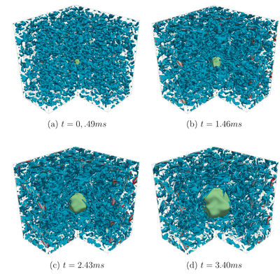
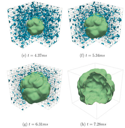
Expanding flames constitute a basic fundamental configuration for pre-mixed laminar and turbulent gaseous combustion. We present a DNS of propane/air 3D expanding flame in a turbulent mixture, performed with the HALLEGRO solver.
- Mesh 480 x480x480 (~110 million grid points) ; dx~60 m ; 3x3x3 cm
- Initial Passot-Pouquet spectrum then cold flow DNS for obtaining decreasing turbulence
- 512 proc, 70 000 CPU hours
- Comparison with EXPERIMENTAL & EEM (asymptotic modeling) approaches
(see also FLAMEX results at [1]) 
|
|
|
LEFT : Three dimensional simulation of a propane/air stoichiometric expanding flame. Iso-contours of vorticity (blue to red) and of reaction rate (green). Physical times range here from 0.49 to 7.28 ms.
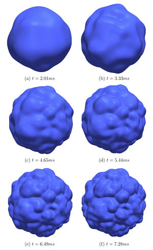
RIGHT : results obtained with FLAMEX, pseudo-spectral/ETDRK solver for a Sivashinsky-type Evolution Equation (written for the whole front surface). 2.36 M colocation points; Fourier-Legendre decomposition. 3 CPU hours...
- More details in E. Albin & Y. D’Angelo, Assessment of the Evolution Equation Modelling approach for three-dimensional expanding wrinkled premixed flames, Combustion & Flame, Vol. 159, Issue 5, pp 1932–1948, May 2012 [2]
Wet combustion analysis (Eric Albin, C O Pashereit & Yves D'Angelo)
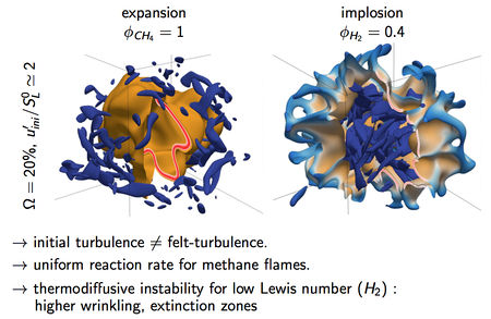
We are interested in DNS of converging and diverging reactive fronts in turbulent mixtures, for wet combustion analysis.
Four different mixtures are used :
Methane/air = 1
Metahne/air/steam = 1
H2/air = 0.4
H2/air/steam = 0, Ω = 0.0 Ω = 0.2 Ω = 0.0 Ω = 0.2
• different flame configurations :
4 laminar expansions 1.5x1.5x1.5
4 laminar implosions 1.5x1.5x1.5
6 turbulent expansions 1.8x1.8x1.8
6 turbulent implosions 1.5x1.5x1.5
→ 20 simulations.
→ between 512 and 4096 processes
→ 2.5 million cpu hours, ≃ 10Tb of analysed data.
|
|
3D NSCBC modeling for transverse and corner outflows (Eric Albin, Luc Vervisch & Yves D'Angelo)
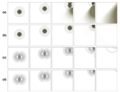
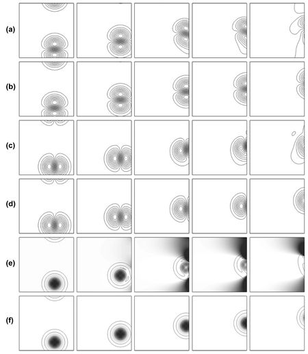
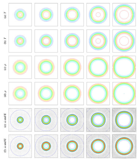
The limitations of usual three dimensional Navier–Stokes Characteristic Boundary Conditions (3D-NSCBC) for flows traveling in a direction that is oblique to the boundary may induce flow deformation at the vicinity of the outflow/ To limit errors generated at boundaries with flows having any arbitrary direction, we propose to organize the wave decomposition in a coordinate system that is attached to the local flow streamline crossing the boundary, because some modeled expressions are not frame independent. Compared to previous 3D-NSCBC, the modified strategy accounting for oblique waves is found to improve the outflow treatment for transverse outgoing vortices, up to vortices crossing an outflow corner. The method is also applied to an expanding laminar flame.
|
Outgoing vortex at upright corner. (a) density field (gray gradients) and Q-criterion iso-lines, 3D-NSCBC; (b) density field and Q-criterion iso-lines, 3D-NSCBC-TOM; (c) iso-U2, 3D-NSCBC; (d) iso-U2, 3D-NSCBC-TOM.
|
|
Left : Outgoing oblique vortex (a) Iso-U1, 3D-NSCBC; (b) iso-U1, 3D-NSCBC-TOM; (c) iso-U2, 3D-NSCBC; (d) iso-U2, 3D-NSCBC-TOM; (e) iso-Q criterion and density (gray gradients), 3D-NSCBC; (f) iso-Q criterion and density, 3D-NSCBC-TOM. Right : 2D expanding laminar premixed flame. (a, c, and e) 3D-NSCBC. (b, d, and f) 3D-NSCBC-TOM. (a and b) Temperature. (c and d) Density. (e and f) Reaction rates and velocity vectors.
More details on
- E. Albin, Y. D'Angelo & L. Vervisch, Flow streamline based Navier-Stokes Characteristic Boundary Conditions: modeling for transverse and corner outflows, Computers and Fluids, 51, 1, pp. 115-126, 2012 http://dx.doi.org/10.1016/j.compfluid.2011.08.005
- E. Albin, Y. D'Angelo & L. Vervisch, Using staggered grids with acoustic boundary conditions when solving compressible reactive Navier-Stokes equations, International Journal for Numerical Methods in Fluids, 2012 http://dx.doi.org/10.1002/fld.2520
No-slip wall acoustic boundary condition treatment in the incompressible limit : the NSWIL strategy (Marianne Cuif Sjöstrand & Yves D'Angelo)
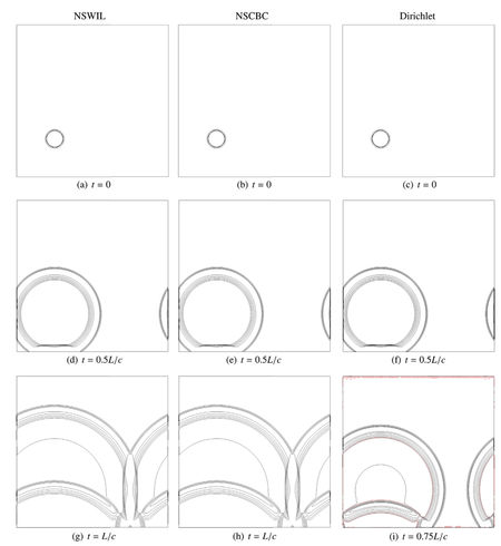
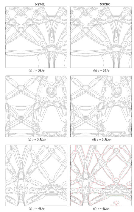
Accurate and stable no-slip wall boundary condition for compressible flows is still an open problem for general high-order finite difference solvers. A characteristic formulation for the numerical treatment of acoustically reflecting no-slip wall boundary condition is presented and numerically validated for some discriminating situations. As an extension of the 3DNSCBC popular approach, this NSWIL strategy relaxes smoothly towards a 3DNSCBC strategy for a slipping wall – the Euler equations natural wall boundary condition – when the viscosity goes to zero. Using our in-house 6th order FD solver, some comparative tests were performed. In particular, we computed a pressure wave train in a 2D periodic channel, leading to standing acoustic waves. Long time runs using NSWIL strategy and involving temporal iterations and more than 2000 acoustic reflections at the walls show no numerical instability while popular NSCBC strategy turns out to be unstable after less than 100 reflections. In that case, global mass conservation was very precisely ensured using NSWIL (relative loss after 2000 acoustic reflections) while NSCBC induced a global variation above 1% before code crashed.
|
|
Left : Comparison of the pressure contours for the acoustic reflection in a 2D box, for respectively 3DNSCBC, NSWIL and Dirichlet BC treatment at the wall, at different acoustic times of the computation. Notice the oscillations close to the lower wall and also along the upper wall, for the Dirichlet approach. Right : Same computation at later acoustic times, for NSWIL and NSCBC strategies. Notice the oscillations close to the lower wall (figure (f), bottom right) for the NSCBC approach, at acoustic time t = 4L/c.
- More details on M. Sjostrand-Cuif, Y. D'Angelo & E. Albin, No-slip Wall Acoustic Boundary Condition treatment in the Incompressible Limit, Computers & Fluids, Volume 86, Pages 92–102, November 2013. [3]
DNS analysis of the non reactive & reactive flow inside a centimetric scale whirl flow combustor (M Cuif Sjöstrand, N Swaminathan & Y D'Angelo)
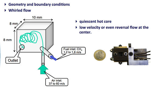
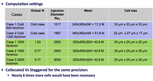
- A quasi–cubic 8×10×8 air/methane non-premixed asymmetric combustion chamber is analyzed by means of direct numerical simulation. Three different cases with Reynolds numbers of 3380 and 4480 and global equivalence ratios of 0.77 and 1.027 were considered. Time-averaged and instantaneous flow dynamics are analyzed. A flame/turbulence interaction scenario can be proposed for this intermittently confined, low-turbulence combustive flow. In addition to the general turbulent flame features, unsteady or specific phenomena (such as interacting flames, ignition and extinction events, pockets of fresh gas burning into the hot core, and flame-relative thickening due to the small scale) were also observed. Available DNS data may be further exploited for RANS/LES SGS model benchmarking in this partially premixed small-scale combustion regime.
- In addition to the expected result that increasing Reynolds numbers intensify turbulent structures, fuel/air mixing, and subsequent combustion, DNS results showed the following :
→ Flow topology was nearly identical for all three considered cases, as shown by our mean streamline observations. Essentially, the main central vortex recirculating zone of hot gases stabilized combustion, which is typical of these confined whirl flows.
→ At a constant Reynolds number (for the air jet), the equivalence ratio increase displaced combustion upstream of the mean flow.
→ A flame/turbulence “flip-flap” interaction, which was the result of a mutual sequential inhibition, led to a throbbing behavior that was experimentally observable (see Liu et al 2010). Additional specific unsteady events (such as tearing-off of fresh gas pockets that penetrated into the central hot burned gas zone, interacting flames, and extinction events) are visible in the instantaneous snapshots. These transient phenomena further influenced the shape of the instantaneous scatter plots of the reaction rate with respect to the mixture fraction Z .
- Future research should investigate i) a more specific combustion regime analysis, ii) a wall heat transfer analysis, and iii) sub-grid scale modeling benchmarking for LES/RANS. In fact, the DNS data made available in our study may be further exploited to test closure validity in this particularly weak, turbulent, partially premixed, small-scale combustion regime.
|
|
HALLEGRO Sample computations. Left : Burning Case N°3 Front position (iso-reaction rate) in its turbulent environment (iso-contour of the Q-criterion). Center : Q-criterion iso-contour for the Cold case N°2 i) Turbulent area at the impact and along the air jet ii) Ring shaped structures at the impact iii) Turbulent structures drop along the main jet of air. Right: Burning Case N°3, another view and another iso-reaction rate.
External Links
See also the DYCO Team Main Page, Yves D'Angelo's page at DYCO/LIED, the DYCO Solvers and the FLAMEX solver web pages.
